|
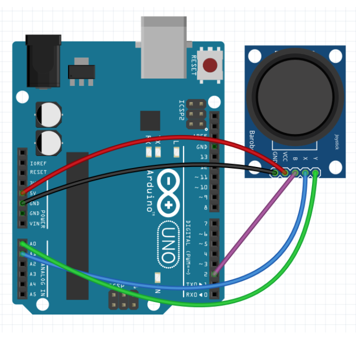
Objective: In this activity you'll learn how to use the left-right action of a joystick to turn on a red LED when the joystick is pushed to the left and a green LED when it's pushed to the right (or vice versa, depending on how you have the joystick oriented). The code: The pre-placed code blocks set up digital pins 12 and 13 (the green and red LEDs) for output, and digital pin 2 (the joystick's B pin) and analog pin A1 (the joystick's X pin) for input. The code then starts a loop that reads the joystick's B pin until it gets a nonzero "high" or "1" signal, indicating that the joystick button was pushed. The code then ends. While the loop is running, the code inside the loop uses two conditional "if-else" statements to check the state of the joystick's X value. The X value ranges from 0 (joystick pushed completely left) to 1023 (pushed completely right). The middle "neutral" value is 512, although the joystick calibration may be slightly off, so that the neutral value is around but not exactly equal to 512. The first "if-else" statement checks to see if the X value is greater than 712. If so, it turns on the green LED. If not, it makes sure the green LED is off. The second "if-else" statement checks to see if the X value is less than 312. If so, it turns on the red LED. If not, it makes sure the red LED is off. (The 712 and 312 values are 512 plus or minus 200, but other values could be used.) Connections (see diagram below): The joystick has five pins: Y, X, B, VCC, and GND. Using male-to-female wires, connect the VCC and GND pins to the 5V and one of the GND pins, respectively, in the Power section of the Arduino. Connect the B (button) pin to digital pin 2 on the Arduino. Connect the X pin to analog pin A1. For this activity we don't need the Y pin (the green wire). For the LED module (not shown on the diagram), plug in its B, G, and R pins to digital pins 11, 12, and 13, respectively, on the Arduino, with the module's "-" pin going in the GND pin.
|

| Grid Size: S M L | Simple View: | MinView: |
| Coord: x-axis y-axis | Grid Lines: x-axis y-axis | |||
| Grid: | 12x12 inches | 24x24 inches | 36x36 inches | |
| 72x72 inches | 96x96 inches | 192x192 inches | ||
| 1x1 inches | 2x2 inches | Fraction: | ||
| xy-Range: | ||||
|
|
||||
|
|
||||
| Quad: | 1 Quadrant | 4 Quadrants | 1&4 Quadrants | |
| Units: | US Customary | Metric | Ruler: | |
| Labels: |
|
|
|
|
Font
px
|
|
| Tics Lines: |
|
Width
px
|
| Hash Lines: |
|
Width
px
|
|
(
,
in
) in
|
|
 degrees
|
|
|
(
,
in
) in
|
|
 degrees
|
|
|
(
,
in
) in
|
|
 degrees
|
|
|
(
,
in
) in
|
|
 degrees
|
|
|
(
,
in
) in
|
|
 degrees
|
|
|
(
,
in
) in
|
|
 degrees
|
|
|
(
,
in
) in
|
|
 degrees
|
|
|
(
,
in
) in
|
|
 degrees
|
|
|
(
,
in
) in
|
|
 degrees
|
|
|
(
,
in
) in
|
|
 degrees
|
|
|
(
,
in
) in
|
|
 degrees
|
|
|
(
,
in
) in
|
|
 degrees
|
|
|
(
,
in
) in
|
|
 degrees
|
|
|
(
,
in
) in
|
|
 degrees
|
|
|
(
,
in
) in
|
|
 degrees
|
|
|
(
,
in
) in
|
|
 degrees
|
|
|
(
,
in
) in
|
|
 degrees
|
|
|
(
,
in
) in
|
|
 degrees
|
|
|
|
Set up the Arduino with LED and joystick and then click the Run button. Move the joystick left or right to turn on the red or green LEDs. Press down on the joystick button to end. Modify the code so that it uses the green and blue LEDs instead of red and green. |
|
Pre-Board Workspace
|
|||||||||||

Post-Board Workspace
|
|||||||||||

