Set Up to Control Arduino Using RoboBlocky
Outline:
- Introduction
- Connecting an RGB LED Module to the Arduino
- Installing Software to Control the Arduino from a Computer
- Connecting the Arduino to the Computer
- Blinking the LED
- Dimming the LED Using the PWM Output Option
- Troubleshooting
- Explore the "Moon Base SOS" and Other Arduino Learning Activities
1. Introduction
This page shows how to set up an Arduino microcontroller board, using an LED module as an example. These components, along with many others, are available in the Barobo Arduino-Compatible Basic Kit and the Arduino-Compatible Starter Kit (classroom bundles available). You will also need a computer (Windows, Mac, or Chromebook machine) to connect to the Arduino board using the USB cable that comes in the kits.
2. Connecting an RGB LED Module to the Arduino
The RGB (“red green blue”) LED module has four pins coming out of it, as shown in Figure 1 below. They are labeled “B”, “G”, “R”, and “-“, standing for blue, green, red, and ground.
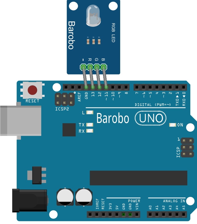
Figure 1: Connecting the RGB LED Module to the Arduino
One side of the Arduino board has a row of sockets labeled 0 through 13 and GND. (Sometimes on diagrams these are labeled D0 through D13, the “D” standing for digital. In addition, even though they are sockets, they are usually referred to as pins.) Plug in the LED module so that its “-“ pin goes in the GND socket, and the R, G, and B pins naturally go in to the 13, 12, and 11 sockets, respectively, as shown in Figure 1.
3. Installing Software to Control the Arduino from a Computer
Once the LED module is connected to the Arduino, the next step is to connect the Arduino to the computer and test the setup. There are two parts to making the connection: a hardware connection via a USB cable (supplied in the Arduino-Compatible Basic Kit or Starter Kit) and a software connection via “ChDuino” software (for Windows and MacOS machines) or “Arduino Controller” software (for Chromebooks).
We will install the software first and then make the hardware connection in the next section. There is one way to install the software for Windows and MacOS machines and a different way to do it for Chromebooks, so we will cover each in turn.
(a) Downloading and Installing ChDuino for Windows and MacOS
For Windows and MacOS machines, the necessary "ChDuino" software comes as part of the free "Linkbot Labs" software. Information to download and install Linkbot Labs is available here. The “Ch” indicates that the software uses the Ch programming language to control the Arduino. But we can also use RoboBlocky's Arduino code blocks to control it.
After you have downloaded and installed the Linkbot Labs software, you can access the ChDuino software using the Launch menu in RobBlocky (Figure 2):
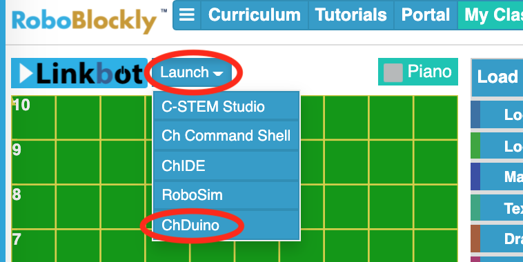
Figure 2: RoboBlocky Launch Menu for ChDuino
Alternatively, ChDuino should appear in the list of applications for your computer and can be launched from there. Its icon looks like this:
![]()
Figure 3: The ChDuino Application Icon
When you open ChDuino, you should see a graphical user interface like that shown in Figure 4. It gives a visual representation of the various pins on the Arduino board, and allows us to control the input and output pins on the board using the interface. You can view the analog voltage values read by the A0-A5 ports on the left side, can view digital input values, and can control the digital output values. For the next step, continue with Section 4 below.
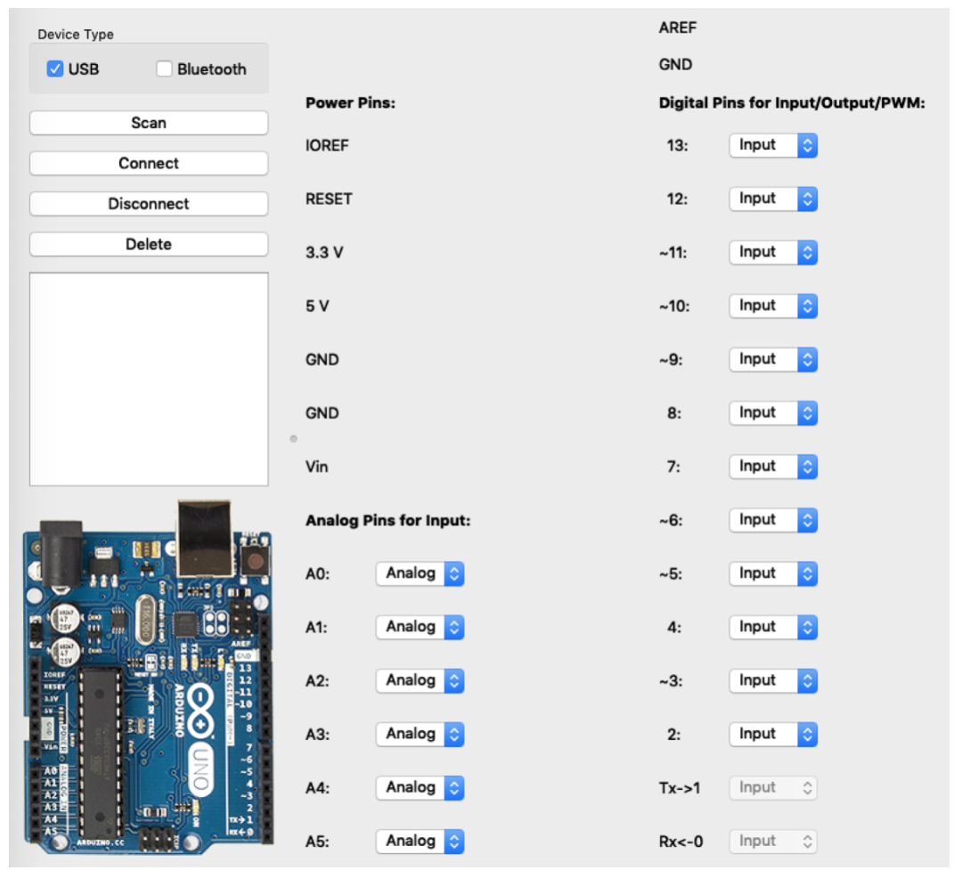
Figure 4: The ChDuino Interface
(b) Downloading and Installing Arduino Controller for Chromebooks
The Arduino Controller software for Chromebooks is available as a free download. To download the latest version, go to the RoboBlocky Downloads page, scroll down to the Chromebook section, and click the link labeled “Arduino Controller extension.” The Arduino Controller page at the Chrome Web Store should be displayed, as shown in Figure 5 below.
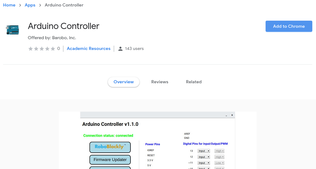
Figure 5: The Arduino Controller Page at the Chrome Web Store (for Chromebook users)
Click the “Add to Chrome” button on the right, and then click the “Add app” button in the popup confirmation window that appears. (If you don’t see the “Add to Chrome” button, but instead it is labeled “Launch app,” it means that you already have Arduino Controller installed as one of your Chrome extensions. Or if it is labeled "Not Compatible," it means that you are not using a Chromebook to access that page.)
After a few seconds the Arduino Controller page will reappear with the “Add to Chrome” button changed to “Launch app.” Click the “Launch app” button. There will be a brief “Loading” message, and then you should see the window shown in Figure 6 below.
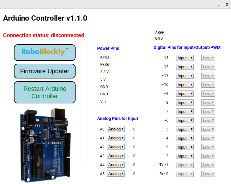
Figure 6: The Arduino Controller Interface for Chromebooks
The Arduino Controller window gives a visual representation of the various pins on the Arduino board, and allows us to control the input and output pins on the board using the interface. You can view the analog voltage values read by the A0-A5 ports (on the left side), can view digital input values, and can control the digital output values (as we will see).
If you lose sight of the Arduino Controller window, click its icon (Figure 7) in the Chromebook “shelf” (the row of apps along the bottom or side of your screen). The icon is a small image of the Arduino board. If you don’t see the icon, then you will need to relaunch the controller by going back to its page in the Chrome Web Store and clicking the “Launch app” button. (Tip: If you’re having trouble finding it again in the Chrome Web Store, go to www.barobo.com/downloads and click the “Arduino Controller” button in the Chromebook section. It will take you to the proper page in the Chrome Web Store. It’s also good to bookmark it, of course.)

Figure 7: The Arduino Controller Icon
4. Connecting the Arduino to the Computer
The next step is to physically connect the Arduino board to the computer. It’s a basic USB connection, using the USB cable supplied in the Arduino Starter Kit. As shown in Figure 8, one end plugs into the large silver socket on the Arduino, and the other end plugs into a regular USB port on the computer.
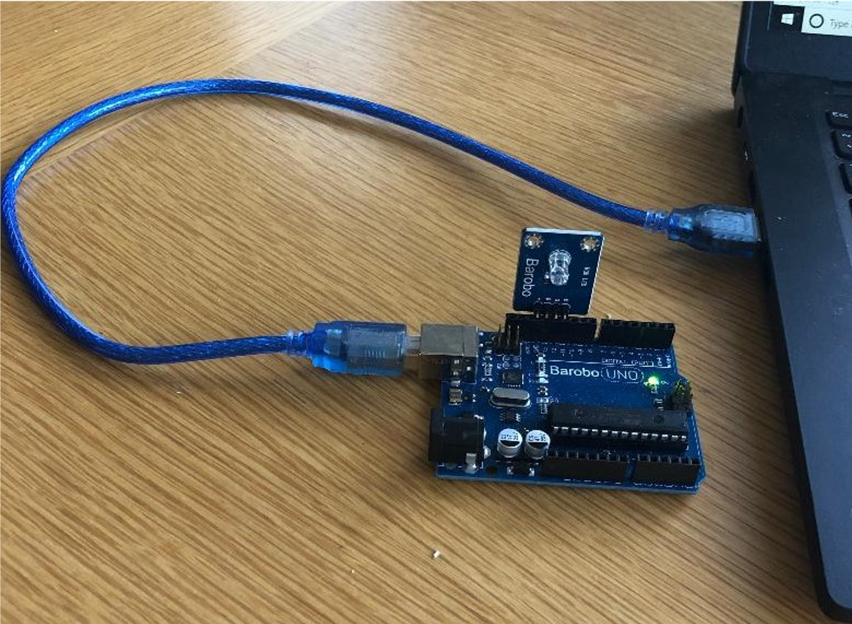
Figure 8: Connecting the Arduino to the Computer via USB cable
Once the Arduino is connected to the computer via the USB cable, you should see a light on the board turn on, indicating it is getting power from the computer (assuming the computer is on).
In order to complete the connection, we need to get the Arduino software (ChDuino for Windows and MacOS machines and Arduino Controller for Chromebooks) to recognize the Arduino board. As usual, the process is slightly different for Windows/MacOS vs. Chromebooks, so we’ll cover each in turn.
(a) Completing the connection for Windows and MacOS machines
If the ChDuino program is not open, you can open it now. Make sure the “USB” checkbox at the top left of the ChDuino interface is checked (and Bluetooth unchecked), and then click the “Scan” button at the top left, and it will scan for a connected Arduino board. Yours should appear in the message area in the middle left, as shown in Figure 9 below, with a red dot next to it. The red dot indicates that the Arduino is physically connected but not yet connected via the software. The COM port where the Arduino is connected may also be listed. (It’s possible to have multiple Arduinos connected to the same computer.)
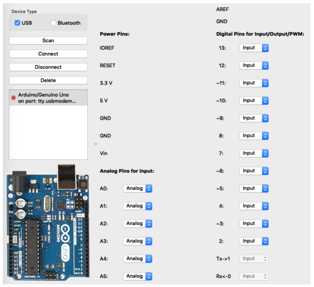
Figure 9: ChDuino Program Interface with Arduino Listed
To complete the connection click the “Connect” button at the top left.
Two things may happen at this point. If you are using a new Arduino, or one that hasn't been used in awhile, the red dot will turn to green, but there will also be a message along the lines of “Check connection or update firmware" (Figure 10):
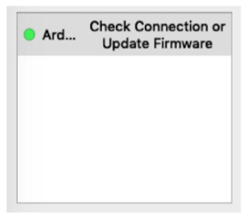
Figure 10: Upload Firmware Message
If you see this message, see the section below on how to update the firmware.
The second thing that may happen when you click the "Connect" button is that the red dot simply turns to green:
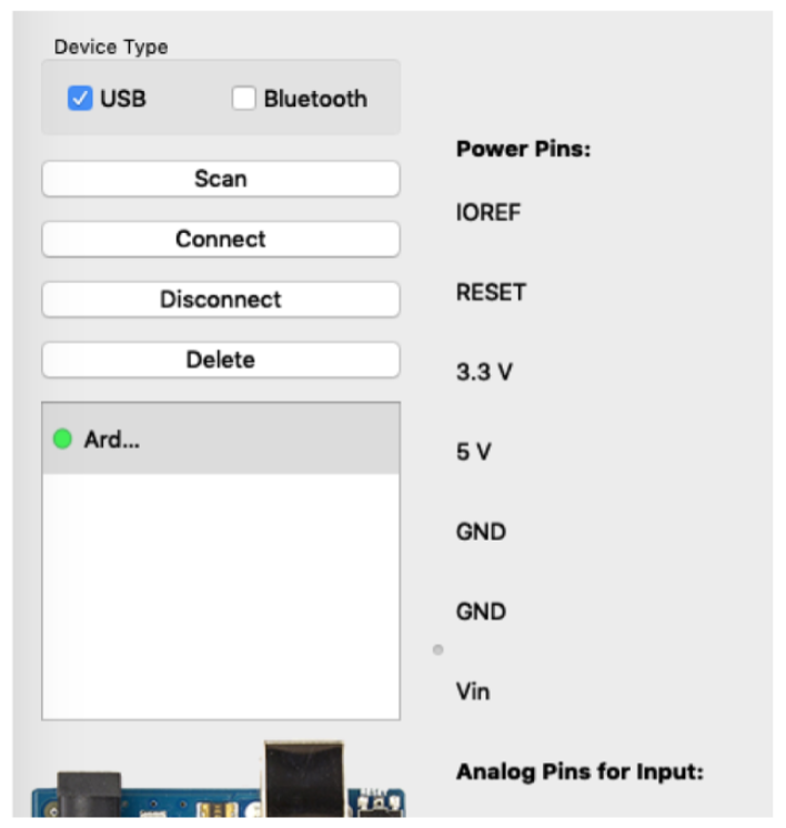
Figure 11: Arduino Connection Complete (green dot)
In addition, fluctuating numbers should appear in the Analog pin section of the ChDuino interface, and you should see a blinking light on the Arduino. All this indicates that the Arduino is properly connected and ready for use.
How to Update Firmware: If, when you click the “Connect” button, the red dot turns to green but there’s also a message along the lines of “Check connection or update firmware,” click the message. A small window should open with a button that allows you to update the firmware on the Arduino board (Figure 12):
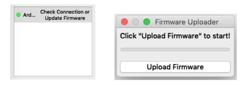
Figure 12: Update Firmware Message and Popup Window
Firmware is the computer code stored on the Arduino that runs the board. When new features are added, or software bugs fixed, a new version of the firmware must be uploaded and stored in the Arduino board.
Click the "Upload Firmware" button. You will see a progress bar that shows that it is uploading (Figure 13):

Figure 13: Upload Firmware Progress Bar
When it is finished, a "Done Uploading" message will appear and the Arduino will be ready to go. If ChDuino does not show the Arduino as connected (with the green dot), simply click the "Connect" button again to reconnect.
You can also manually update an Arduino board's firmware by going to ChDuino's Tools menu and selecting "Firmware Uploader." To do this the Arduino board should not already be connected via ChDuino, so if it is, first click the Disconnect button. (Of course, the Arduino must be physically connected to the computer with the USB cable.) When you select the "Firmware Uploader" option in the Tools menu, you will see a popup window something like this (Figure 14):
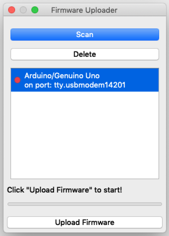
Figure 14: Manual Option to Update Firmware
Click "Upload Firmware" and the firmware uploading process will start. (If no Arduino board is listed, first click "Scan.")
For the next step, continue with Section 5 below.
(b) Completing the connection for Chromebooks
Completing the connection for Chromebooks is simple. Make sure that the Arduino Controller is running and its window is visible (relaunch it and/or click its icon in the shelf to bring it forward, if necessary). Once the Arduino Controller is running, as soon as you plug in the Arduino board’s USB connection the Controller software recognizes it and makes the connection. The message near the top left of the Arduino Controller window will change from “Connection status: disconnected” to “Connection status: connected” in green, as shown in Figure 15. (If you physically disconnect the USB cable, the message will be “Connection status: error” in red. Plugging it back in should reset things and give the “Connection status: connected” message after a few seconds.)
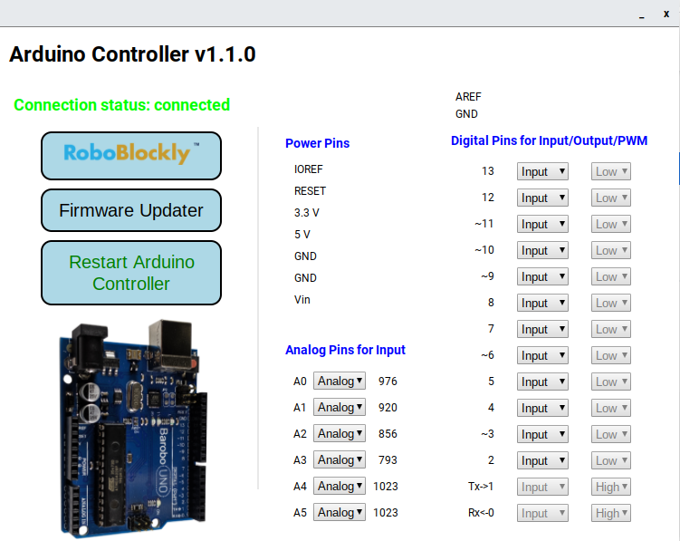
Figure 15: “Connected” Message Showing Arduino Connection is Complete (Chromebooks)
In addition, fluctuating numbers should appear in the Analog pin section of the Arduino Controller window, and you should see some blinking lights on the Arduino. This all indicates that the Arduino is properly connected and ready for use.
Note: If you physically plug in the Arduino’s USB cable to the Chromebook before launching the Arduino Controller software, everything will still work. When the Arduino Controller is launched, it should recognize that an Arduino board is plugged in and make the connection, yielding the “Connection status: connected” message.
You probably have also noticed that there is a “Firmware Updater” button in the Arduino Controller window. Firmware is the computer code stored on the Arduino that runs the board. When new features are added, or software bugs fixed, a new version of the firmware must be uploaded and stored in the Arduino board. At times you may get a message to the effect of “firmware update needed.” If so, click the “Firmware Updater” button. A popup window like that shown in Figure 16 should appear. Click “Start” and wait until the progress bar reaches 100%, then close the Firmware Uploader window.
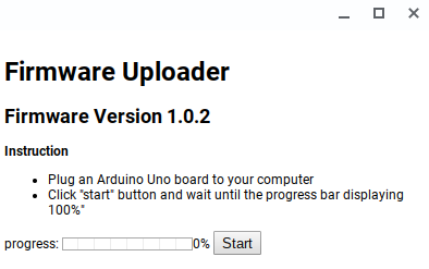
Figure 16: Firmware Uploader Window for Chromebooks
If you’re not sure if you have the latest version of the firmware installed, it’s fine to go through the upload firmware process. If the current firmware on board is the same as the firmware being uploaded, the “new” firmware will replace the current firmware, but there will of course be no difference in the end result, and everything should run fine
5. Blinking the LED
At this point you should have the LED module connected to the Arduino board, and the Arduino board connected to the computer via the USB cable and the ChDuino interface (for Windows and MacOS machines) or the Arduino Controller (for Chromebooks).
The final step is to send a High signal to the LED to turn it on (or Low to turn it off). The red LED is connected to the Arduino’s digital pin 13. Because we want to output a signal from the Arduino to the LED, we need to set pin 13 to “Output” mode using the pulldown menu next to the pin number in ChDuino or Arduino Controller. For the ChDuino interface, if pin 13 is set to “Input”, it looks like this:
![]()
Figure 17: The Input/Output Pulldown Menu for Digital Pin 13 (ChDuino for Windows/MacOS)
Click on the pulldown menu and change it to “Output” and it will look like this:
![]()
Figure 18: The Output High/Low Options for Pin 13 (ChDuino for Windows/MacOS)
For the Arduino Controller interface, changing pin 13 to Output looks like slightly different:
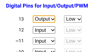
Figure 19: The Output High/Low Interface for Pin 13 (Arduino Controller for Chromebooks)
To output a “turn on” signal to the LED, simply click the “High” radio button for pin 13 in the ChDuino interface or use the pulldown menu for pin 13 in the Arduino Controller interface to select “High.” A 5 volt signal will be sent through pin 13 to the LED, thus turning it on. To turn it off, simply click the “Low” button (ChDuino) or select “Low” (Arduino Controller), which sends a 0 volt signal to the pin and out to the LED.
You can also try turning on/off the blue light by outputting a High or Low signal on pin 11 and turning on/off the green light by doing the same for pin 12. It’s fine to turn on multiple lights at the same time. For example, turning on the red and blue LEDs at the same time gives a purple effect
6. Dimming the LED Using the PWM Output Option
It’s also possible to get a “dimmer switch” effect using certain of the Arduino’s digital pins. Normally, a digital device is either on (High voltage) or off (Low or 0 voltage). But using a technique known as “pulse width modulation” (PWM), it’s possible for a digital pin on the Arduino to simulate a range of voltage outputs. When an LED is connected to a digital pin set to the PWM mode, the simulated range of voltage outputs allows the brightness of the LED to be varied over the range from Low (off) to High (full on).
If you look closely at the numeric labels for the digital pins on the Arduino board, you will see that some of them have a tilde (squiggly line) in front of the number. This indicates that the pin can be set to PWM mode in addition to Input or Output mode. You can also see the tilde indicators in the ChDuino interface (Windows and MacOS machines), though not in the Arduino Controller interface (Chromebooks). In both ChDuino and Arduino Controller, however, you can see which pins have the PWM option by clicking on the Input/Output menu for that pin. If it’s a PWM pin, then you will see PWM as a third option. For reference, the PWM pins are digital pins 3, 5, 6, 9, 10, and 11.
To try out the PWM dimmer effect, use ChDuino or the Arduino Controller to set pin 11 (connected to the blue LED) to PWM. Figure 20 shows how ChDuino and Arduino Controller display the PWM option with a slider control.
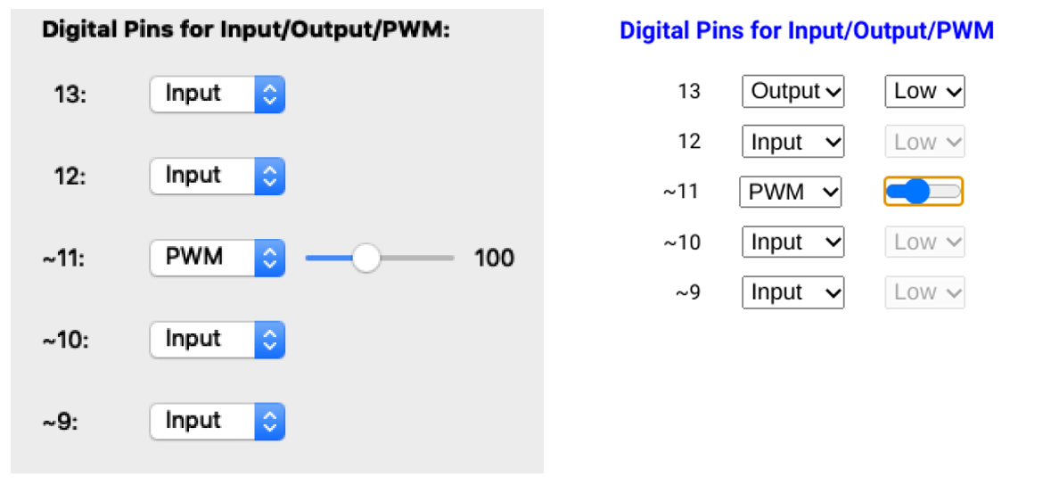
Figure 20: Setting Pin 11 to PWM Output (ChDuino on the left, Arduino Controller on the right)
7. Troubleshooting
So that’s how you connect an Arduino board to a computer and control an LED. If your LED does not turn on and off when you click “High” and “Low” in ChDuino or Arduino Controller, here are some things to check:
-
Is the Arduino board connected properly and running? (Check for green power light, plus blinking lights on the board.)
-
Is ChDuino (Windows/MacOS) or Arduino Controller (Chromebook) running and connected to the Arduino? (Check for green dot in ChDuino or “connected” message in Arduino Controller, and check that analog values are shown as fluctuating.)
-
Is the LED connected to the proper pin, and is that the pin you are using in ChDuino or Arduino Controller to turn it from High (on) to Low (off)?
-
Is the pin set to “Output”?
-
If you are using a breadboard to create a circuit (not just an LED module as in the above example), does your wiring match that shown in the wiring diagram? (It’s easy to have one of the wires or other connections be in the wrong place, or not completely plugged in.)
8. Explore the “Moon Base SOS” and Other Arduino Learning Activities
You are now all set to go to https://roboblocky.com/curriculum/hourofcode/arduino/ and explore the “Moon Base SOS” activities that use the LED device, or the other Arduino learning activities at https://roboblocky.com/curriculum/arduino/.
